Toy OS 1: From Power-On to the MBR
Toy OS worklog: 1. Real mode · 2. Segmentation · 3. Paging · 4. Kernel · 5. Interrupts · 6. Buddy · 7. Slab · Source
toy-os is a small 32-bit x86 kernel I am writing from scratch. I want to see what happens between power-on and a kernel that hands out memory, not just read about it. It runs in the Bochs emulator. The boot path follows 《操作系统真相还原》 and navi’s 从零开始写 OS 内核 series. For memory management I copy Linux’s design, as described in Understanding the Linux Kernel (ULK).
The source code is on GitHub: twicy/toy-os. These worklogs cover the code up to commit fc88a1d (2026-10-20), one milestone per post:
- Real mode: from power-on through the BIOS to the MBR (this post)
- Segmentation and the GDT
- Protected mode and paging
- Loading the kernel
- Interrupts, the PIC and the timer
- Physical memory: E820, memblock and the buddy system
- Slab and kmalloc
Every address in these posts comes from the real thing: Bochs’s debugger, readelf, or the toy-os screen.
Table of Contents
- Setup
- Power-on: the first instruction
- The BIOS loads sector 0 to 0x7C00
- Real-mode addressing and the first MiB
- The MBR
- References
Setup
The tools:
- Bochs 2.8, with the
bochsandbochs-xpackages, 512 MiB of RAM and the legacy BIOS image (BIOS-bochs-legacy). The sound card needssound: driver=dummy, and the keyboard is set withkeyboard:, because the oldkeyboard_mapping:option is gone. - nasm for the boot code, and later
gcc -m32andldfor the kernel (post 4). - A flat disk image,
toy-os.img, with 20 cylinders × 16 heads × 63 sectors. The Makefile writes each binary into it withdd.
dd if=./mbr.bin    of=./toy-os.img bs=512 count=1   conv=notrunc
dd if=./loader.bin of=./toy-os.img bs=512 count=4   seek=2 conv=notrunc
dd if=./kernel.bin of=./toy-os.img bs=512 count=200 seek=9 conv=notrunc
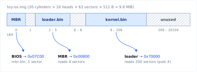
Where each binary sits on the disk, and who reads it into memory.
On a HiDPI screen, Bochs’s own X11 window is tiny and cannot be scaled. So make run starts Bochs with its VNC server (display_library: rfb) and opens it in Remmina, scaled up. Two catches: the Bochs VNC server only speaks 8-bit color, and it panics on the X11 keymap files, so it runs without one. The old window is still there as make run-x11. The screenshots in these posts come straight from that VNC framebuffer.
Power-on: the first instruction
A reset puts the CPU in real mode, the 16-bit mode of the 8086. Real-mode addresses are segment × 16 + offset, yet the first instruction does not come from CS × 16 + IP. Here is the Bochs debugger at instruction 0, before anything has run (trimmed):
Next at t=0
(0) [0x0000fffffff0] f000:fff0 (unk. ctxt): jmpf 0xf000:e05b          ; ea5be000f0
rip: 00000000_0000fff0
cs:0xf000, dh=0xff0093ff, dl=0x0000ffff, valid=7
	Data segment, base=0xffff0000, limit=0x0000ffff, Read/Write, Accessed
CR0=0x60000010: pg CD NW ac wp ne ET ts em mp pe
CS holds 0xF000, but its base is 0xFFFF0000, not 0xF000 × 16 = 0xF0000. Every segment register has a hidden part, the descriptor cache, holding the base and limit the CPU actually uses. At reset the CPU loads a special value into it, so the first fetch is at 0xFFFF0000 + 0xFFF0 = 0xFFFFFFF0, 16 bytes below 4 GiB. The chipset maps the BIOS ROM there. That ROM has room for one instruction, a far jump: jmpf 0xf000:e05b reloads CS the normal real-mode way (base 0xF0000), and the BIOS carries on from its copy at 0xFE05B in the first MiB. (Post 2 is about this hidden part.)
CR0.PE = 0 (lower-case pe above) means real mode. The cache is also off (CD, NW) until the BIOS turns it on.
The BIOS loads sector 0 to 0x7C00
The BIOS runs its power-on self test (POST), sets up the interrupt vector table and its data area, finds the disks and prints a banner. Then it walks the boot order. For a hard disk, it reads LBA 0 (512 bytes) to 0000:7C00. If the last two bytes are 0x55 0xAA, it jumps there. I set a breakpoint at 0x7C00:
(0) Breakpoint 1, 0x0000000000007c00 in ?? ()
Next at t=7109628
(0) [0x000000007c00] 0000:7c00 (unk. ctxt): jmpf 0x0000:7c48          ; ea487c0000
rax: 00000000_0000aa55
rdx: 00000000_00000080
rsp: 00000000_0000ffd6
The BIOS ran 7.1 million instructions before the first byte of toy-os. DL = 0x80 is the boot drive (the first hard disk). AX = 0xAA55 is probably left over from the signature check.
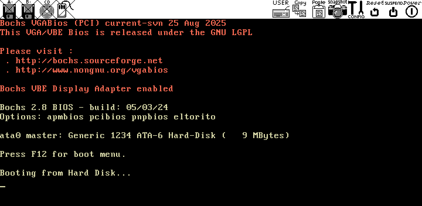
The screen at that breakpoint. The BIOS has printed “Booting from Hard Disk…” and toy-os has not run yet.
Why 0x7C00? The usual explanation goes back to the IBM PC 5150. Its smallest model had 32 KiB of RAM, and its BIOS put the boot sector in the last 1 KiB of it: 0x8000 − 0x400 = 0x7C00, leaving 512 bytes above the sector for its data and stack.
Real-mode addressing and the first MiB
In real mode a segment register is just a number: the physical address is segment × 16 + offset. That gives 20 bits, 1 MiB. FFFF:FFFF would be 0x10FFEF, but the 8086 had only 20 address lines, so the address wrapped around to 0x0FFEF. Later CPUs keep that wrap-around until the A20 line is enabled (post 3).
This is the first MiB at the moment the MBR runs, with the two pieces toy-os has placed so far:
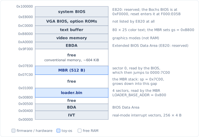
Physical memory below 1 MiB when the MBR runs (not to scale). “free” means unused RAM.
0x00000–0x004FF: the real-mode interrupt vector table (256 × 4-bytesegment:offsetpairs) and the BIOS Data Area. The BIOS needs both, and they must not be overwritten while the code still makes BIOS calls.0x07C00–0x07DFF: the MBR. It setssp = 0x7C00, so its stack grows down from just below itself.0x00800–0x00FFF: where the MBR puts loader.bin, 4 sectors. It used to be at0x900, as in the book, and moved to0x800in a later revision. The E820 memory map (post 6) sits just below it, at0x500–0x784.0x9F000–0x9FFFF: the Extended BIOS Data Area. From0xA0000up it is not RAM at all: video memory (the color text buffer is at0xB8000), the VGA BIOS ROM at0xC0000, and the system BIOS at the top.
The MBR
The MBR has 510 bytes of code and data, plus the signature. It does four things: it sets up the segment registers, clears the screen and prints, reads the loader, and jumps to it.
Segments and stack
%include "boot.inc"
SECTION MBR vstart=0x7c00
    jmp 0x0:mbr_entry
    ...
mbr_entry:
    xor ax,ax
    mov ds,ax
    mov es,ax
    mov ss,ax
    mov sp,0x7c00
    mov fs,ax
    mov ax,0xb800
    mov gs,ax
vstart=0x7c00 makes nasm assemble every label as an offset from 0, starting at 0x7C00. That only works if CS = 0. Most BIOSes jump to 0000:7C00, but some jump to 07C0:0000, which is the same physical byte with a different CS. The far jump at the top makes CS:IP = 0000:7C48 either way. (That is the jmpf 0x0000:7c48 in the debugger output above.) gs = 0xB800 points at the text buffer.
Printing through the BIOS
In real mode the BIOS does the work. int 10h with AH = 06h scrolls the window up, which clears the screen, and AH = 02h puts the cursor at the top left. The print routine lives in util.inc, shared by the MBR and the loader. It reads the cursor (AH = 03h), then writes the string (AH = 13h), which handles CR LF itself:
; cx should hold character count
; es:bp should point to the string
print_real_mode:
    ; get cursor position, dh = row, dl = col
    ; it also returns the cursor shape in cx, so save the count
    push cx
    mov ah,0x03
    mov bh,0x0
    int 10h
    pop cx
    ; Write string
    mov ah,0x13
    mov al,0x01
    mov bh,0x0
    mov bl,0x07
    int 10h
    ret
%include pastes the file where the directive is, so util.inc must go somewhere execution cannot fall into. It also refuses to assemble outside 16-bit code (%if __?BITS?__ != 16 / %error). Once the loader switches to 32-bit code, BIOS calls are gone for good.
Reading the loader with ATA PIO
There is no file system, just sectors. The MBR talks to the primary ATA controller through I/O ports, in 28-bit LBA mode:
| Port | Write | Read |
|---|---|---|
0x1F0 |
data, one 16-bit word at a time | |
0x1F2 |
sector count | |
0x1F3–0x1F5 |
LBA bits 0–23 | |
0x1F6 |
0xE0 | LBA bits 24–27 (LBA mode, master drive) |
|
0x1F7 |
command: 0x20 = read sectors |
status: BSY (bit 7), DF (5), DRQ (3), ERR (0) |
After the command, the drive raises DRQ once per 512-byte sector, and each sector is 256 in ax, dx reads from the data port:
    ; the drive raises DRQ once per sector, wait before each one
.next_sector:
    ; reading 0x1f7 returns status
    ; status lags behind the command / last data word by up to 400ns
    ; 4 reads give the drive that time, so stale bits are not trusted
    mov dx,0x1f7
    in al,dx
    in al,dx
    in al,dx
    in al,dx
.not_ready:
    in al,dx
    ; bit 7 BSY = 1: the other bits are not valid yet
    test al,0x80
    jnz .not_ready
    ; bit 5 DF device fault, bit 0 ERR
    test al,0x21
    jnz disk_error
    ; bit 3 DRQ = 0: sector data not ready yet
    test al,0x08
    jz .not_ready

    ; data port, 256 words = one 512 byte sector
    mov dx,0x1f0
    mov cx,256
.go_on_read:
    in ax,dx
    mov [bx],ax
    add bx,2
    loop .go_on_read

    dec di
    jnz .next_sector
    ret
The first version (b5e42cb) did what the book does: it waited for DRQ once, then read count × 256 words in one go. That works in Bochs, but the protocol says to wait before each sector, and the status is only valid about 400 ns after the last access. In the revision (cbd7402) the MBR waits per sector, checks DF and ERR, and prints “Disk read error” and halts on failure. The MBR has no caller to return an error to, so halting is all it can do.
Then come the jump and the signature:
    mov eax,LOADER_START_SECTOR     ; LBA 2
    mov bx,LOADER_BASE_ADDR         ; 0x800
    mov cx,4
    call read_disk
    ...
    jmp LOADER_BASE_ADDR

times 510-($-$$) db 0
db 0x55,0xaa
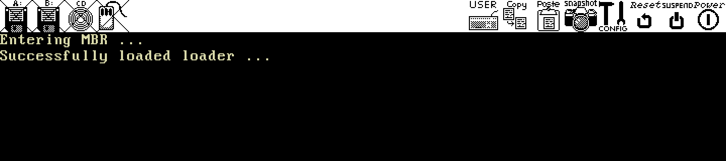
Stopped at 0x800, the loader’s first instruction. Both lines were printed by the MBR through int 10h.
Two things have to stay in sync between the Makefile and the assembly (both are in my commit notes):
- The
seek=2in the Makefile must matchLOADER_START_SECTORinboot.inc. - The
ddcountmust match the number of sectors the MBR reads (mov cx, ...), and both must cover the wholeloader.bin. At first the loader was smaller than one sector, socount=1andmov cx, 1were enough. Once it grew protected-mode code (post 3), it no longer fit, so both are now 4 (2 KiB;loader.binis 881 bytes).
Next, the loader leaves real mode. First it needs a GDT, the subject of post 2.
References
- 郑钢, 《操作系统真相还原》, ch. 2 (编写 MBR 主引导记录) and ch. 3 (完善 MBR): the MBR, the real-mode memory layout, and reading the disk through ports.
- navi, 从零开始写 OS 内核 - BIOS 启动到实模式, segmentfault.
- D. P. Bovet and M. Cesati, Understanding the Linux Kernel, 3rd ed., Appendix A “System Startup”: the BIOS and the boot loader.
- OSDev Wiki, ATA PIO Mode and Memory Map (x86).
- Intel 64 and IA-32 Architectures Software Developer’s Manual, Vol. 3A, “Processor Management and Initialization”: the reset state and the first instruction executed.