Toy OS 5: Interrupts, the PIC and the Timer
Toy OS worklog: 1. Real mode · 2. Segmentation · 3. Paging · 4. Kernel · 5. Interrupts · 6. Buddy · 7. Slab · Source
The kernel prints (post 4), but it runs with IF = 0, the way the loader left it, and it has no IDT. A divide by zero would end in a triple fault and a reboot. This post adds the Interrupt Descriptor Table, a common entry path for all 256 vectors, the 8259A interrupt controller and a 100 Hz timer. (These were the commits 18ae789, 14a9b9a and 4a3564b.)
Table of Contents
- Vectors
- The IDT
- 256 stubs and one common path
- A first test: int3
- The 8259A PIC
- The PIT and a 100 Hz tick
- PANIC turns interrupts off first
- References
Vectors
Every interrupt or exception arrives as a vector number, 0–255:
- 0–31: CPU exceptions. Intel reserves all of them, defined or not. Examples: 0 divide error, 3 breakpoint, 6 invalid opcode, 8 double fault, 13 general protection, 14 page fault. Some of them (8, 10–14, 17, 21) push an error code on the stack. The others do not.
- External interrupts come from devices through an interrupt controller, which the OS programs to use vectors of its choosing. toy-os uses 0x20–0x2F.
- Software interrupts:
int nraises vector n.int3(one byte,0xCC) is the breakpoint.
Most exceptions are either faults, where the saved EIP points at the instruction that faulted so it can be retried (page fault), or traps, where it points at the next instruction (int3). A few are aborts (double fault, machine check), which cannot be resumed at all.
The IDT
The IDT works like the GDT (post 2): a table of 8-byte descriptors, found through a register, IDTR. Each entry is a gate that holds a selector:offset pointing at the handler:
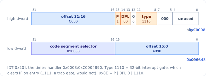
The gate for vector 0x20, as Bochs’s info idt decodes it below.
/* With only Interrupt Gate Descriptors, nested interrupts cannot happen
 * Trap Gate Descriptors does not clear IF so interrupts are not masked
 */
struct interrupt_descriptor {
    uint16_t offset_15_0;
    uint16_t segment_selector;
    uint8_t zero;
    uint8_t type_attr;
    uint16_t offset_31_16;
} __attribute__((packed));

/* P = 1, DPL = 00b, Type = 1110b */
#define INTER_DESC_TYPE_DEFAULT 0x8E

void init_idt(void) {
    for (int i = 0; i < IDT_SIZE; i++) {
        idt[i].offset_15_0 = intr_stubs[i] & 0xFFFF;
        /* Index + TI + DPL */
        idt[i].segment_selector = 0b1000;
        idt[i].zero = 0;
        idt[i].type_attr = INTER_DESC_TYPE_DEFAULT;
        idt[i].offset_31_16 = intr_stubs[i] >> 16;
    }
    struct idt_ptr idtr;
    idtr.limit = sizeof(idt) - 1;
    idtr.base = (uint32_t)idt;
    asm volatile ("lidt %0" : : "m" (idtr));
}
All 256 gates are 32-bit interrupt gates. Entering one clears IF, so a handler cannot be interrupted, and nesting is impossible for now. A trap gate (type 1111) would leave IF alone. The table is 2 KiB of .bss at 0xC0007E20:
<bochs> info idt 0 4
Interrupt Descriptor Table (base=0x00000000c0007e20, limit=2047):
IDT[0x00]=32-Bit Interrupt Gate target=0x0008:0xc0004780, DPL=0
IDT[0x01]=32-Bit Interrupt Gate target=0x0008:0xc0004789, DPL=0
IDT[0x02]=32-Bit Interrupt Gate target=0x0008:0xc0004792, DPL=0
...
<bochs> info idt 32 34
IDT[0x20]=32-Bit Interrupt Gate target=0x0008:0xc0004890, DPL=0
IDT[0x21]=32-Bit Interrupt Gate target=0x0008:0xc0004899, DPL=0
Two privilege checks, from my notes on the commit (ULK ch. 4 walks through them):
- The handler’s code segment DPL must be ≤ CPL. A handler can never be less privileged than the code it interrupts. All gates use selector
0x08, the ring 0 kernel code, so this always passes. - For a software interrupt (
int n,int3,into), CPL ≤ gate DPL, or the CPU raises #GP instead. Every gate here has DPL 0, so a ring 3 program cannotint 0x20and pretend to be the timer. A system call gate will be the one gate with DPL 3. Hardware interrupts and CPU exceptions skip this check.
256 stubs and one common path
The CPU tells the handler nothing about which vector brought it there, and only some exceptions push an error code. So each vector gets a tiny stub that makes the stack look the same every time. nasm’s %rep writes all 256:
%define HAS_ERRCODE(v) ((v) == 8 || ((v) >= 10 && (v) <= 14) || (v) == 17 || (v) == 21)

section .text

%assign vec 0
%rep 256
stub_%[vec]:
; If this vec has no err code, push placeholder
%if !HAS_ERRCODE(vec)
    push 0
%endif
    push vec
    jmp intr_common
%assign vec vec + 1
%endrep

intr_common:
    ; Predefined order: eax, ecx, edx, ebx, esp, ebp, esi, edi
    pushad
    push esp
    cld
    call intr_dispatch
    add esp, 4
    popad
    ; the err code/placeholder + the vec
    add esp, 8
    iretd

section .rodata
intr_stubs:
%assign vec 0
%rep 256
    dd stub_%[vec]
%assign vec vec + 1
%endrep
A stub is 9 bytes (push 0, push imm8, jmp rel32). The 8 vectors with an error code skip push 0 and take 7. That explains the IDT targets above: 0xC0004780 + 24 × 9 + 8 × 7 = 0xC0004890 for vector 0x20. intr_stubs is the table of stub addresses that init_idt copies into the gates.
When intr_dispatch starts, the stack holds a complete frame. push esp passes its address as the argument, and the C struct below describes it:
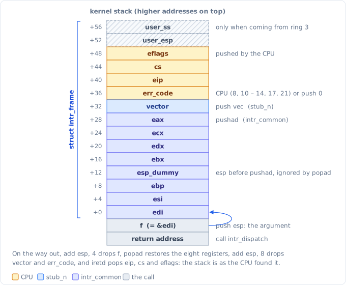
Who pushes what. user_esp and user_ss are only there when the interrupt came from ring 3, which cannot happen yet.
struct intr_frame {
    uint32_t edi, esi, ebp, esp_dummy, ebx, edx, ecx, eax;
    uint32_t vector, err_code;
    uint32_t eip, cs, eflags;
    uint32_t user_esp, user_ss;
};
The cld matters. The C calling convention guarantees the direction flag is clear when a function is called, but an interrupt can arrive in the middle of code that set it, such as a backwards rep movsb. Without cld, any memcpy in a handler would run backwards.
The C side is a table of function pointers, plus a fallback that names the exception and halts:
void intr_dispatch(struct intr_frame *f) {
    /* Fall thru APIC vector range */
    if (f->vector >= PIC_IRQ_BASE && f->vector < PIC_IRQ_BASE + PIC_IRQ_COUNT) {
        if (!pic_ack(f->vector - PIC_IRQ_BASE)) {
            return;
        }
    }

    if (intr_handlers[f->vector]) {
        intr_handlers[f->vector](f);
    } else {
        unhandled_intr(f);  // "exception 13 (general protection), err 0x..., eip 0x..."
    }
}
A first test: int3
static void on_breakpoint(struct intr_frame *f) {
    printk("int3 at eip %#x\n", f->eip);
}
...
    register_handler(3, on_breakpoint);
    asm volatile ("int $3");
    printk("back from int3\n");
It prints int3 at eip 0xc0001815, yet int3 itself is at 0xC0001814:
c0001814:	int3
c0001815:	sub    $0xc,%esp
int3 is a trap, so the saved EIP is the next instruction, and iretd resumes there: “back from int3”. A debugger that patches 0xCC over an instruction has to back EIP up by one to re-run it.
The 8259A PIC
Device interrupts go through two Intel 8259A chips. The master takes IRQ 0–7. The slave takes IRQ 8–15 and signals the master on the master’s IRQ 2. The CPU sees one interrupt line (INTR), asks the PIC for a vector, and goes through the IDT:
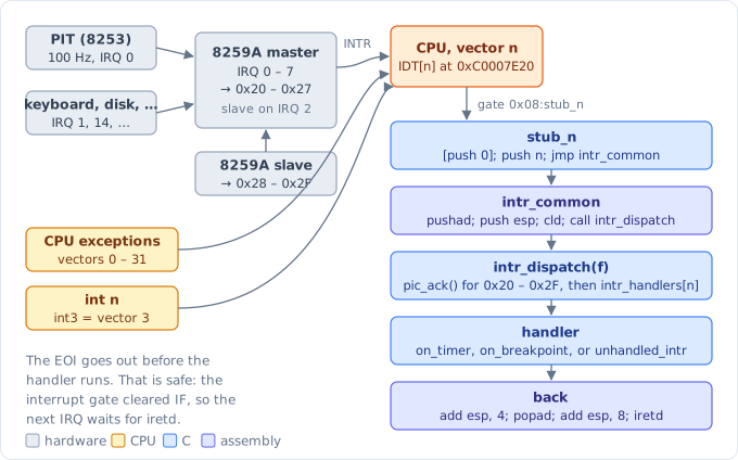
From a device to a C handler and back.
The BIOS leaves the master on vectors 0x08–0x0F. Those are CPU exceptions in protected mode: an untouched timer IRQ 0 would arrive as vector 8, a “double fault”. So the first job is to remap both chips, with four initialization command words (ICW) each:
void init_pic(void) {
    /* ICW1 on the command port, ICW2-4 then follow on the data port */
    outb(PIC_MASTER_CMD, ICW1_INIT_ICW4);   // 0x11: init, cascaded, edge, ICW4 follows
    outb(PIC_SLAVE_CMD, ICW1_INIT_ICW4);

    /* ICW2: vector of the chip's IRQ 0, the low 3 bits must be 0 */
    outb(PIC_MASTER_DATA, PIC_IRQ_BASE);        // 0x20
    outb(PIC_SLAVE_DATA, PIC_IRQ_BASE + 8);     // 0x28

    /* ICW3: the master gets a bitmask of the pins with a slave on them,
     * the slave gets the number of the master pin it hangs off */
    outb(PIC_MASTER_DATA, 1 << IRQ_CASCADE);
    outb(PIC_SLAVE_DATA, IRQ_CASCADE);

    outb(PIC_MASTER_DATA, ICW4_8086);       // 8086 mode, EOI sent by software
    outb(PIC_SLAVE_DATA, ICW4_8086);

    /* OCW1: mask everything but the cascade, drivers unmask their own IRQ */
    outb(PIC_MASTER_DATA, (uint8_t)~(1 << IRQ_CASCADE));
    outb(PIC_SLAVE_DATA, 0xFF);
}
(The real code has an io_wait(), a write to the unused POST port 0x80, after each ICW, because real 8259As need a moment between them.)
After delivering an IRQ, the PIC holds back IRQs of equal or lower priority until it gets an end-of-interrupt (EOI, 0x20 on the command port). An IRQ from the slave is in service on both chips, so both need an EOI. intr_dispatch sends it before calling the handler. That is safe because the interrupt gate has cleared IF: a new IRQ can be raised at the PIC but will not reach the CPU before iretd.
pic_ack also catches spurious IRQs. If a device drops its line before the CPU acknowledges it, the PIC still has to answer with a vector, so it hands out its lowest-priority one: IRQ 7 (master) or 15 (slave). It does not mark it in service, though, so reading the in-service register tells the two apart:
int pic_ack(uint8_t irq) {
    if (irq == 7 || irq == 15) {
        uint16_t cmd = irq == 7 ? PIC_MASTER_CMD : PIC_SLAVE_CMD;
        outb(cmd, OCW3_READ_ISR);
        if (!(inb(cmd) & 0x80)) {
            /* The master did see the cascade IRQ 2, only the slave's was fake */
            if (irq == 15) {
                outb(PIC_MASTER_CMD, OCW2_EOI);
            }
            return 0;
        }
    }
    /* An IRQ from the slave is in service on both chips */
    if (irq >= 8) {
        outb(PIC_SLAVE_CMD, OCW2_EOI);
    }
    outb(PIC_MASTER_CMD, OCW2_EOI);
    return 1;
}
The PIT and a 100 Hz tick
The 8253/8254 programmable interval timer counts down from a divisor at 1.193182 MHz. In mode 2 (rate generator), channel 0 raises IRQ 0 every time it reaches zero and reloads:
#define PIT_INPUT_HZ 1193182
/* Channel 0 (bits 7-6 = 00), low byte then high byte (bits 5-4 = 11),
 * mode 2 rate generator (bits 3-1 = 010), binary count (bit 0 = 0) */
#define PIT_CMD_CH0_RATE 0x34

/* volatile: an IRQ changes it behind the back of any loop reading it */
static volatile uint32_t ticks;

static void on_timer(struct intr_frame *f) {
    (void)f;
    ticks++;
    if (ticks % TIMER_HZ == 0) {
        printk("uptime %u s\n", ticks / TIMER_HZ);
    }
}

void init_timer(void) {
    uint16_t divisor = PIT_INPUT_HZ / TIMER_HZ;     // 11931, i.e. 100.007 Hz

    outb(PIT_CMD, PIT_CMD_CH0_RATE);
    outb(PIT_CHANNEL0, divisor & 0xFF);
    outb(PIT_CHANNEL0, divisor >> 8);

    register_handler(PIC_IRQ_BASE + IRQ_TIMER, on_timer);
    pic_unmask(IRQ_TIMER);
}
Then, for the first time since the loader’s cli in post 3:
    init_timer();
    /* IF has been 0 since the loader's cli, IRQs only arrive from here on */
    asm volatile ("sti");
    for (;;) {
        /* sleep until the next interrupt instead of spinning */
        asm volatile ("hlt");
    }
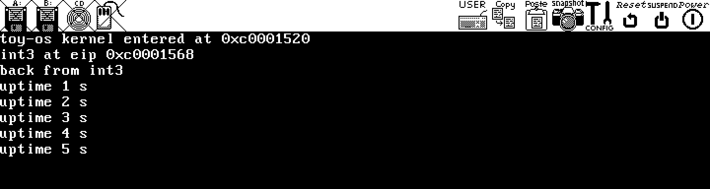
The kernel at commit 14a9b9a, stopped after the fifth “uptime” line. main was at 0xC0001520 back then.
PANIC turns interrupts off first
The next commit (4a3564b) added PANIC and ASSERT. My note on it: interrupts need to be disabled before PANIC.
/* cli first: with IF set, the next IRQ wakes hlt and its handler keeps
 * printing over the panic message */
#define PANIC(...) do { \
    asm volatile ("cli"); \
    printk("PANIC at %s:%d %s(): ", __FILE__, __LINE__, __func__); \
    printk(__VA_ARGS__); \
    printk("\n"); \
    for (;;) { \
        asm volatile ("hlt"); \
    } \
} while (0)
hlt only sleeps until the next interrupt. With IF still set, the timer would wake the CPU 100 times a second, on_timer would print “uptime” lines under (and eventually over) the panic message, and the system would look half-alive. With cli, hlt really is the end; only an NMI could wake it.
main still has an ASSERT(1 == 2) right after sti, as a test. In the current build the compiler knows the assertion always fails, so sti is followed directly by cli:
c000182a:	sti
c000182b:	cli
c000182c:	push   $0xc00062b0
sti only takes effect after the next instruction, which is cli. So no tick ever gets in, and the screen ends like this:
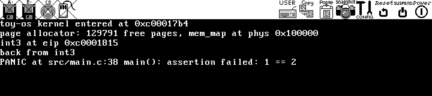
toy-os at fc88a1d, the end of this series. The “page allocator” line comes from post 6.
References
- 郑钢, 《操作系统真相还原》, ch. 7 (中断): the IDT, the 8259A, interrupt stubs with error-code placeholders, and the 8253 timer.
- navi, 从零开始写 OS 内核 - 中断处理, segmentfault.
- D. P. Bovet and M. Cesati, Understanding the Linux Kernel, 3rd ed., ch. 4 “Interrupts and Exceptions”: IRQs and the PIC, the IDT, the hardware’s privilege checks, and why Linux sets most gates to DPL 0.
- Intel 64 and IA-32 Architectures Software Developer’s Manual, Vol. 3A, “Interrupt and Exception Handling”: the exception table, error codes, gate descriptors, and the interrupt shadow of
sti. - OSDev Wiki, 8259 PIC (including spurious IRQs) and Programmable Interval Timer.