RoCEv2: Past, Present and Beyond
InfiniBand (IB), which is the original RDMA technology, defines its own stack from the physical layer up to the transport layer (L1–L4), making it incompatible with the commodity Ethernet/IP infrastructure we have.
RDMA over Converged Ethernet (RoCE), on the other hand, runs on standard Ethernet. RoCEv1 is a plain Ethernet (layer 2) protocol, so it cannot cross IP routers; RoCEv2 adds UDP/IP headers so it can be routed like any other IP traffic. This makes RoCEv2 more scalable and much cheaper than IB equipment, making it a good choice for data centers.
Historically, IB is mostly used in the HPC community. More recently, RoCEv2 has been widely utilized in HPC, AI/ML, and storage in data centers.
RoCEv2 packet
RoCEv2 encapsulates an RDMA transport packet within an Ethernet/IP/UDP packet (IPv4 or IPv6). This makes RoCEv2 compatible with our existing networking infrastructure. The UDP header is needed for ECMP-based multi-path routing.
- The destination UDP port is always set to 4791, while the source UDP port is randomly chosen for each queue pair.
-
The intermediate switches use standard five-tuple hashing. Thus, traffic belonging to the same QP follows the same path, while traffic on different QPs (even between the same pair of communicating end points) can follow different paths.
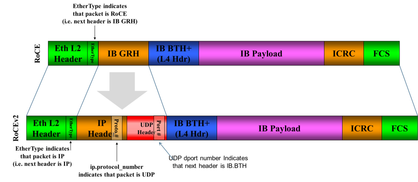 Image source: Nvidia Documentation on RoCEv2
Priority-based Flow Control (PFC)
To create a lossless L2, RoCEv2 uses PFC to avoid Ethernet switch overflow by forcing upstream entity to pause data transmission when encountering congestion.
- How it works:
- PFC is a hop-by-hop protocol between two Ethernet nodes.
- Packets are queued in up to eight queues, each mapping to a priority. At the receiving ingress port, packets are buffered in corresponding ingress queues.
- Once the ingress queue length reaches a certain threshold (XOFF), the switch sends out a PFC PAUSE frame to the corresponding upstream egress queue.
-
Once the ingress queue length falls below another threshold (XON), the switch sends a pause with zero duration to resume transmission.
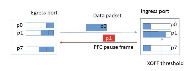
Image source: RDMA over Commodity Ethernet at Scale
- Headroom reservation:
- Need to reserve space for in-flight frames before PAUSE frame hits upstream port
- Size of the headroom is decided by: MTU, PFC reaction time, propagation delay
- Implementation: DSCP-based PFC is favored over VLAN-based PFC (by Microsoft), because layer-3 IP forwarding is more scalable than MAC-based layer-2 bridging
What could go wrong with PFC?
- PFC Deadlock:
- Caused by flooding broadcast of switch when serving packets with valid ARP table entry, invalid MAC address table entry
- Deadlock of switches sending Pause Frames to upstream port
- NIC PFC Pause Frame Storm: a single malfunctioning NIC may block the entire network
Retransmission: Go-Back-N
- Unlike TCP transports, which assume a lossy L2, therefore implementing state machines and SACK to do retransmission; RoCEv2 and IB transport assume lossless L2, therefore, their retransmission scheme is simply Go-Back-N (historically Go-Back-0).
- Go-Back-N means retransmission starts from the first dropped packet: packets received before it are not retransmitted, but every packet sent after it is, even if it arrived.
2015: DCQCN (Microsoft, Mellanox)
Original Paper: Congestion Control for Large-Scale RDMA Deployments
Background:
- PFC is coarse grained, with a granularity of port (and priority) and not flow, leading to a few problems:
- Unfairness: PFC pauses every flow on a port and priority alike, no matter which flows caused the congestion.
-
Victim flow: Cascading PAUSE frames paralyze irrelevant flows
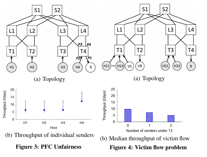 Image source: Congestion Control for Large-Scale RDMA Deployments
What DCQCN does:
- Congestion control algorithm implemented in Mellanox NICs (and not the switches)
- Reaction Point (flow sender): When receiving Congestion Notification Packets (CNP), reduce current rate and restore later (fast recovery + linear addition)
- Notification Point (flow receiver): When receiving ECN-marked packets, generate CNP packets (how and when determined by the algorithm mathematically)
- Congestion Point (switch): Mark packet with ECN when suffering from congestion
Note that DCQCN has been implemented in Mellanox NICs, and has been deployed in Microsoft’s datacenters.
Also note that: Though DCQCN helps reduce the number of PFC pause frames, it is PFC that protects packets from being dropped as the last defense.
2015: TIMELY (Google)
Original Paper: TIMELY: RTT-based Congestion Control for the Datacenter
Why RTT over ECN?
- RTT directly reflects latency
- Further, an ECN mark describes behavior at a single switch
- RTT can be measured accurately in practice (using latest NIC hardware features)
- RTT is a rapid, multi-bit signal (capturing the full extent of end to end queueing delay)
TIMELY framework (implemented in host software with NIC hardware support):
- RTT measurement to monitor the network for congestion
- a computation engine that converts RTT signals into target sending rates
- a control engine that inserts delays between segments to achieve the target rate
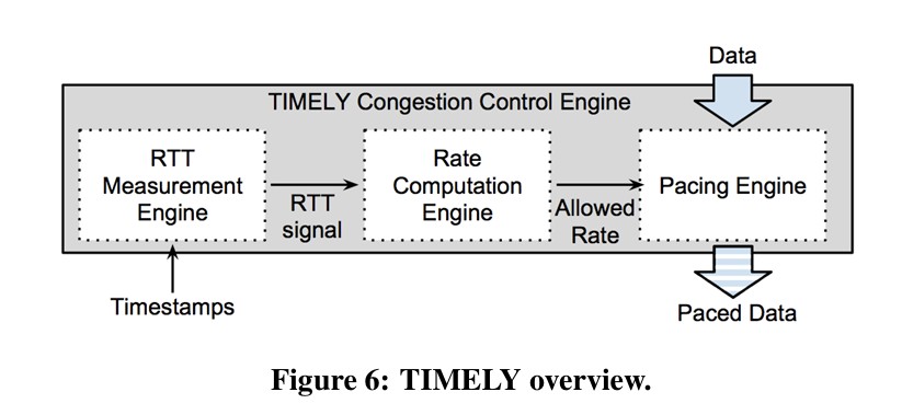
Important assumptions/Why RTT works here?
- Typically, packets going through different network paths have disparate delays, but in datacenters, all paths have small propagation delays
-
The turnaround time at the receiver to generate the ACK is almost 0 here, because the NIC hardware instead of system software handles it
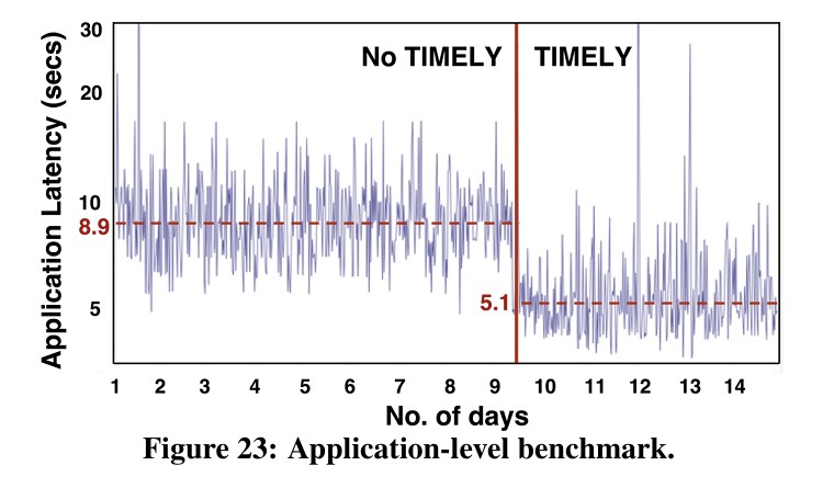
Following TIMELY, the first author of DCQCN published ECN or Delay: Lessons Learnt from Analysis of DCQCN and TIMELY (CoNEXT 2016), arguing that an ECN-based approach is better than an RTT-based one for RDMA.
2020: Swift (Google)
Original Paper: Swift: Delay is Simple and Effective for Congestion Control in the Datacenter
Swift still adopts an RTT-based approach, adapted and evolved from TIMELY. The authors made three key points
- Delay as a congestion signal has proven effective (with the virtue of simplicity)
- It is important to respond to both fabric and host congestion.
- TIMELY only considers fabric congestion
- The paper’s reason: with faster links, the hosts themselves (CPU, PCIe, NIC) became a frequent bottleneck, adding delays of several µs that are no longer negligible in a data center
- We must support a wide range of traffic patterns including large-scale incast
- What DCQCN lacks
- By supporting even a congestion window of less than one
Swift uses many TCP congestion control concepts and ideas (AIMD)
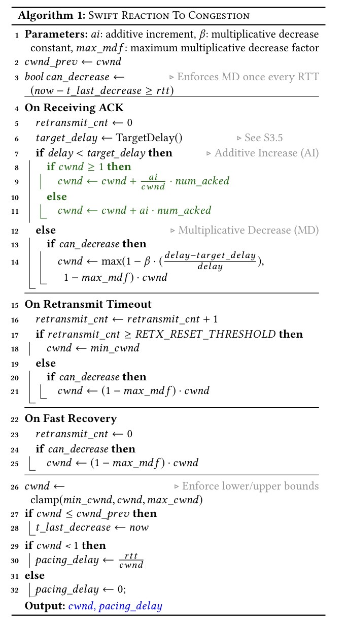
Key points:
- Compared with TCP Reno, which only shrinks its window on packet loss (a timeout or 3 duplicate ACKs), Swift checks the measured delay on every ACK and shrinks its window when the delay exceeds the target, at most once per RTT
- On timeout, where TCP would do slow start deterministically, Swift selectively does slow start/fast recovery based on a threshold
- Swift indeed follows the same AIMD philosophy but has much more tunable parameters
- Swift considers both fabric and host congestion, the actual congestion window =
min(fcwnd, hcwnd)
Fabric Target Delay Scaling:
- Topology-based Scaling:
- #Hops matters!
- Measure the forward path hop count by subtracting the received IP TTL values from known starting TTL, and reflect it back in the ACK header.
- Flow-based Scaling:
- N flows contending for the same switch
- Adjusted in proportion to $\frac{1}{\sqrt{cwnd}}$ (Using cwnd to approximate $\frac{1}{N}$)
- Overall target:
- $\text{base} + f(\text{#Hops}) + f(\text{cwnd})$
Swift Loss Recovery is also like TCP:
- SACK
- Retransmission Timeouts
2018: IRN (Mellanox, UC Berkeley)
The above mentioned congestion control mechanisms naturally assume that a lossless L2 and thus PFC is needed. This paper, Revisiting Network Support for RDMA, tries to prove that the need for PFC is an artifact of current RoCE NIC designs rather than a fundamental requirement.
improved RoCE NIC (IRN) Design:
- Goal: make minimal changes to the RoCE NIC design in order to eliminate its PFC requirement
- Improving the loss recovery mechanism: TCP like SACK
- Basic end-to-end flow control (termed BDP-FC)
- BDP = bandwidth-delay product of the network
- Dividing the BDP of the longest path in the network (in bytes) with the packet MTU set by the RDMA queue-pair (typically 1KB in RoCE NICs).
Key comparison with iWARP
- No TCP congestion window control, AIMD (although the authors later mentioned that AIMD logic further improves its performance)
- Operates directly on RDMA segments instead of bytestream
Implementation:
- RoCE NICs already support per-packet ACKs for Writes and Sends, but not read
- Add Read ACK/NACK
- Supporting Out-of-order Packet Delivery
- DMAs OOO packets directly to the final address in the application memory and keeps track of them using bitmaps; # sized at BDP cap, but still too large for NIC SRAM
- First packet issues: critical information is only carried in the first packet of a message
- WQE matching issues: how to map packets to WQE
- Last packet issues: Finish processing the last packet no longer marks finishing processing the entire message (e.g. before generating CQE)
- Application-level Issues: New writes can be overwritten by retransmission of old writes
Modern RDMA
Revisiting RoCEv2 Design
In the past decades, researchers have been revisiting some of the fundamental design principles in RoCE (mostly on lossless/lossy L2, in-order/out-of-order).
Original Paper: Datacenter Ethernet and RDMA: Issues at Hyperscale
RoCE uses InfiniBand’s simple transport layer that heavily builds on in-order delivery as well as go-back-n retransmission semantics that essentially require a highly reliable in-order fabric for efficient operation.
RoCE’s semantics, load balancing, and congestion control mechanisms are inherited from InfiniBand. This implies that all messages should appear at the destination in order as if they were transmitted over a static route, essentially disallowing many packet-level load balancing mechanisms.
For AI training workloads which are long-lived flows, multi-pathing mechanisms can greatly improve the job completion time.
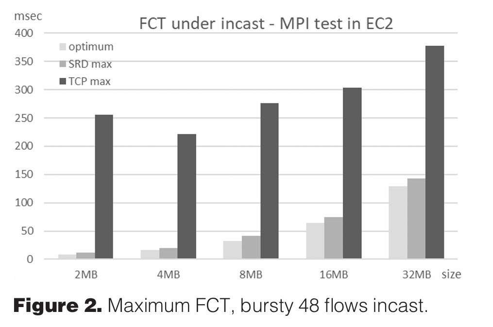
2020: Scalable reliable datagram (SRD) (Amazon)
Original Paper: A Cloud-Optimized Transport Protocol for Elastic and Scalable HPC
Supplementing Document: Add SRD documentation
Key Design:
- Multipath Load Balancing:
- Packet spray instead of ECMP (hash collision hotspots)
- Out of Order Delivery:
- Directly deliver packets to the host
- Done by messaging layer above SRD
- Congestion control:
- Prevent queue buildup and packet drops (rather than relying on them for congestion detection)
- Similar to BBR, based on RTT-indicated per-connection dynamic rate limit
2025+
- Falcon (Google)
- Original Paper: Falcon: A Reliable, Low Latency Hardware Transport
- veRoCE (ByteDance)
- Spec: 字节跳动 veRoCE 传输协议
Both of them:
- Support out-of-order transmission
- Switch from lossless to lossy RDMA
- Support RTT based congestion control
References
- Congestion Control for Large-Scale RDMA Deployments
- RDMA over Commodity Ethernet at Scale
- TIMELY: RTT-based Congestion Control for the Datacenter
- Swift: Delay is Simple and Effective for Congestion Control in the Datacenter
- Revisiting Network Support for RDMA
- Datacenter Ethernet and RDMA: Issues at Hyperscale
- Falcon: A Reliable, Low Latency Hardware Transport